There comes a time in every man’s life when he remembers he has a job and goes and buys an RC car. That time for me came a couple of weeks ago and man is this thing fun. I’ve been tearing up the local middle school dirt track. This past weekend, however, whilst lying around doped up from wisdom teeth removal, I decided to do my first mod.
I was walking through a RadioShack looking for cool stuff (they used to sell cool stuff), and I came across a Mesmic 2125 Dual Axis Accelerometer (you should read how this thing works, it’s actually pretty fascinating). I thought, why not slap this puppy on my RC car so I can track acceleration?
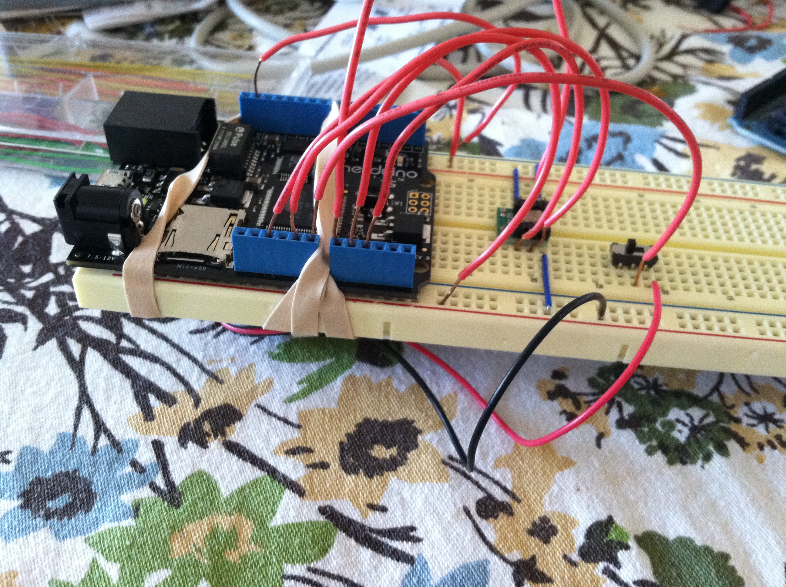
First I wired it up to my Netduino (which rocks by the way). Turns out I actually understood the diagram.
My workbench may also be our kitchen table…
Anyway, I’ve also got a switch on there for controlling the 9v power supply. This was surprisingly easy. The surprisingly tricky part, was actually the software (surprising because I write software for a living).
I don’t know how much Arduino-ing you’ve done, but my Netduino has a bunch of analog inputs that are easy enough to read from and you get a value from 0 to 1023. The tricky part; however, is that the output of the accelerometer is not a single value of the current acceleration, it’s a waveform. I guess this is basic stuff for people that actually know more about electricity than V=IR, but the accelerometer uses something called pulse width modulation.
Essentially, the output from the accelerometer is a square wave, and the length of the high end of the square wave is the value I can derive the acceleration from. A regular Arduino has a method called pulseIn that measures the high or low end of the PWM wave, but my Netduino, for some reason, does not. After a few minutes of googling, I found a clever solution using interrupts. That, combined with my weak understanding of the accelerometer documentation yielded the following AccelerometerPulseInput class:
using System;
using Microsoft.SPOT;
using Microsoft.SPOT.Hardware;

namespace TheGoldenMule.Arduino.Telemetry
{
    public class AccelerometerPulseInput
    {
        private readonly InterruptPort _port;
        private DateTime _time;

        public float PulseWidth
        {
            get;
            private set;
        }

        public AccelerometerPulseInput(Cpu.Pin pin)
        {
            _port = new InterruptPort(pin, false, Port.ResistorMode.Disabled, Port.InterruptMode.InterruptEdgeBoth);
            _port.OnInterrupt += new NativeEventHandler(OnInterrupt);
        }

        private void OnInterrupt(uint data1, uint state, DateTime time)
        {
            if (0 == state)
            {
                // end of pulse
                PulseWidth = (float)((((TimeSpan)(time - _time)).Ticks / 10000.0) - 5);
            }
            else
            {
                // start of pulse
                _time = time;
            }
        }
    }
}
What’s going on?
Well using an InterruptPort, I actually get a C# event when a pin switches from high to low or from low to high. No, I don’t properly grasp what incredible things allow C# to receive hardware interrupts. Anyway, since I’m looking for the high end, I start a timer when the wave goes high, and end it when it goes low. Then I have to divide and subtract as per the accelerometer documentation. That’s my daggum pulse width (actually, it’s the gs of acceleration after I divide and subtract).
The Less Interesting Parts
Once I have the accelerometer values, I write them to an SD card. I wrote a class that just buffers up a few and writes them when the buffer is at some predefined maximum length. That’s fairly uninteresting, but is included in the source on GitHub.
I also wrote a quick AIR app (seriously, with AIR it took 10 minutes) that would plot the data from the SD card. This is also on GitHub, but I’m not going to discuss it here…
The Super Interesting Part
I rubber banded my creation to the battery cover and took it for a test run.
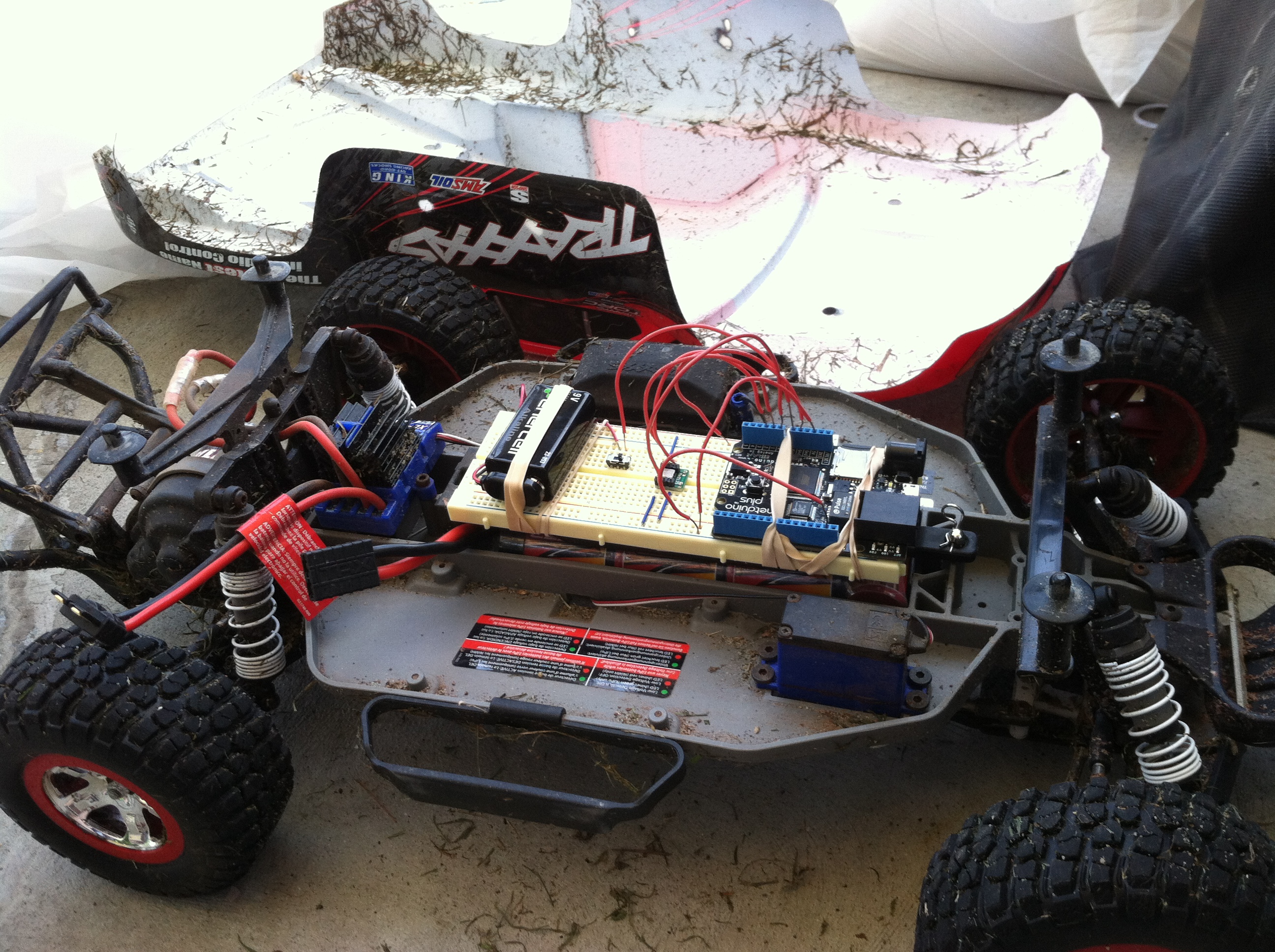
Then brought over the logs from the SD card. Behold!

COOL HUH!?!!???!!!!
I’m actually really surprised that it all worked. But here are real data points. The y-axis measures acceleration in gs. The x-axis is time. It’s not seconds or milliseconds, it’s kinda arbitrary at the moment, but it’s time nonetheless. The blue is acceleration along the x-axis, and the red is acceleration along the y-axis.
Take a look on GitHub.
One Comment
Comments are closed.